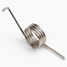
Left-hand and right-hand descriptions can be ambiguous without a viewing direction. A useful drawing gives manufacturing, inspection and assembly teams one common orientation.
Lock the viewing direction
Show the end from which the spring is viewed and add an arrow for the actual loading direction. Winding hand alone does not fully describe operation.
Separate free and installed angles
The free leg angle, assembly preload angle and maximum working angle are different values. Preload changes starting torque and available travel.
Allow body and mandrel clearance
The coil-body diameter can change as a torsion spring works. Mandrel and housing clearances must include direction of operation, diameter change, tolerance and friction.
Accept by torque points
Specify torque at at least one angle and use two points when rate matters. Keep fixture grip positions and loading speed consistent during inspection.
References
This article is informed by public standards catalogues and industry engineering resources. Project values should be confirmed by drawings, material certificates and sample validation.